After some initial tests and research, we decided to go with the “skinny” mecanum drive layout for our competition robot. This robot would have the following features:
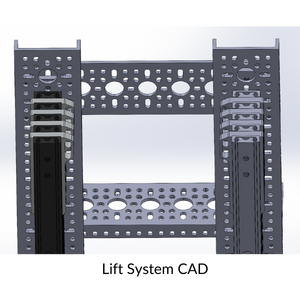
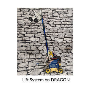
We use the Long Robotics LRS300 linear slide system as it is a robust slide system to effectively move our intake vertically.
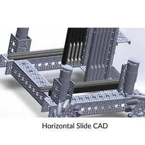
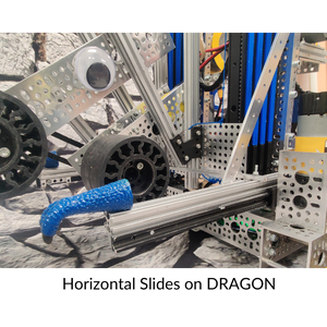
Version 1: We developed a vertical slide system, using a GoBilda Speed servo and two Long Robotics LRS300 slides, that allows us to move our entire lift and intake mechanism on the X-axis as well as the Y-axis. This allows the intake to pick up and score cones from greater distances, helping reduce cycle times.
Version 2: Our original version used a speed servo to move the slides forward and back. The problem was that when holding the slide forward the power required appeared to be putting too much strain on the servo. We replaced it with a higher torque servo to solve this problem. We also designed a custom two-stage spool, which provides more torque and is easier to maintain compared to stock options.
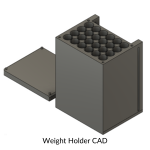
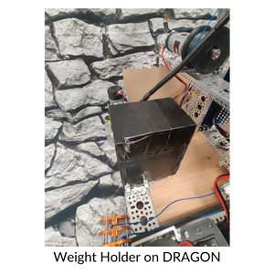
In order to improve weight distribution, we designed a weight holder in Fusion 360. Containing over 30 pounds of weight, it significantly lowers the center of mass of the bot. This helps keep it planted on the ground, even with the lift fully extended.
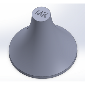
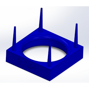
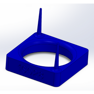
We designed a custom scoring beacon using Solidworks. The final iteration fulfills all size requirements, while also allowing for stacking on the cones and modular with our lift system. To retain strength, 20% printer infill, cubic subdivision infill pattern, and stress-distributing fillets were all utilized. We also reduced the amount of spires from four to two as it would reduce printing times and interference with our intake system, while still providing sufficient redundancy in case one breaks on the field.
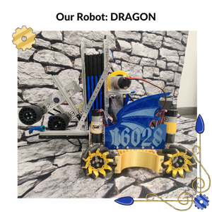
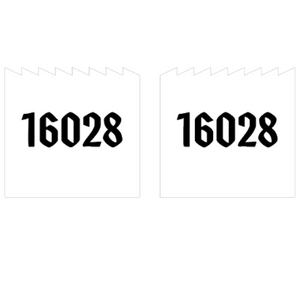
Version 1: To make our robot more aesthetically pleasing and provide light protection for its internals on the field, side panels were designed using Illustrator. The pattern on the plates were chosen for its resemblance to the scales on a dragon, while the font chosen for the numbers hearkens to our medieval theme.
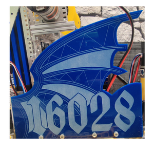
Version 2: The side panels were redesigned in Illustrator to resemble a dragon's wing. Instead of wood, glossy blue acrylic was laser cut as its more on brand with our team's color scheme. In addition, we designed and 3D printed a lower panel using Solidworks. This allows the robot to smoothly slide past poles, while the eye-catching gold improves the bot's aesthetics.

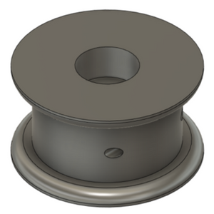
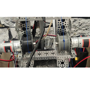
Version 1: To power our vertical lift system, we used a custom, wide spool. Originally designed for Freight Frenzy, this spool we designed last year helped increase our lift’s speed and reliability by keeping the lifting string tightly fastened.
Version 2: As a single spool could not sufficiently lift the spool, we 3D printed a second spool, and attached it to a second motor. This allows one spool to drive one side of the lift, increasing power, lift times, and adding redundancy if one motor fails.
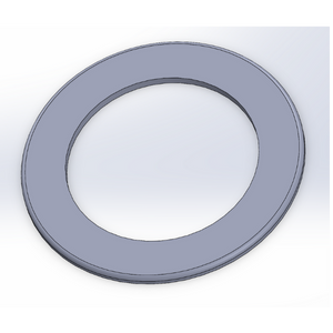
Version 2.1: We had issues with the life string slipping off the spools, which would effectively disable the entire system. To solve the problem, we designed specially-sized disks, 3D printed them, and attached them to the sides of the spool. This remedied the issue by keeping the string tightly on the spool, while the yellow color-scheme keeps the robot on brand.
The Monday after kickoff, our team discussed all aspects of Power Play and gave the highest importance to the following parts of the game:
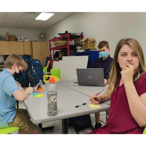
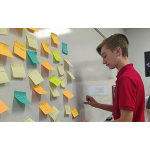
We divided our team into our groups to analyze the game manual as well as possible ways for our robot to accomplish the elements of the game that we decided were the most important. We spent a week gathering information, culminating in a sticky-note brainstorming session, which helped us generate a wide variety of ideas.
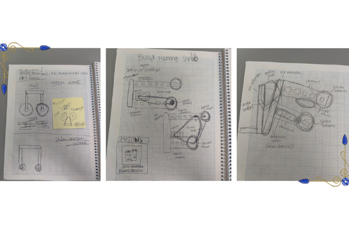
We decided to sketch multiple iterations of our intake and try out which ones would work best.
Version 1: Initially, we tried a cascading lift (a stringing method where all lift stages are moved simultaneously) utilizing fishing line. However, after stringing, we realized that the lift could not be powered to go high enough.
Version 2: Afterwards, we tried to string the fishing line using a hybrid between cascading stringing and continuous stringing (where only one lift stage is moved at a time). This caused reliability issues, with the fishing line slipping off the lift or snapping completely.
Version 2.1: We tried the hybrid method again using stronger paracord. While solving some issues, the stringing method combined with paracord strained the motors, which led to slow lifting times.
Version 3: We decided to test pure continuous stringing, using blue micro cord. This combination turned out to be optimal, as it provided a good balance between strength and speed. In addition, the blue color of the micro cord helps keep our robot on brand.
We wanted to find out how much torque we needed for the motors on our lift to be able to lift our intake. We needed to find how much force is needed to lift the lift, stall torque, and the torque of the spool. To find how much torque is needed to lift our lift we used a handheld scale and measured how much weight it was, 1.7kg x 9.8 m/s^2 = 16.66N. For our stall torque we took the numbers off of REV Robotics website, 4.2Nn. Finally to find the torque of the spool we measured the diameter and got the radius from it, 0.0246m. We then took our radius and multiplied it by how much force is needed to lift our lift and that gave us the torque of the spool, 16.66N x 0.0246m = 0.41Nm.
We then took our torque and divided it by the spool torque, 0.41Nm/0.105Nm = 3.9Nm. After, we multiplied it by the number of stages in our lift and by 1.2, 3.9 x 4 x 1.2 = 18.72. That is the lowest gear ratio we needed to lift our lift. We took rounded that up to 19:1 motor by a factor of 1.7. We did not feel we could increase the speed of the motor to that extent, as the equation modeled an ideal situation, so we instead increased it to a safer 1.5 .
Website by Soul Seed Academy ©2023